Overview
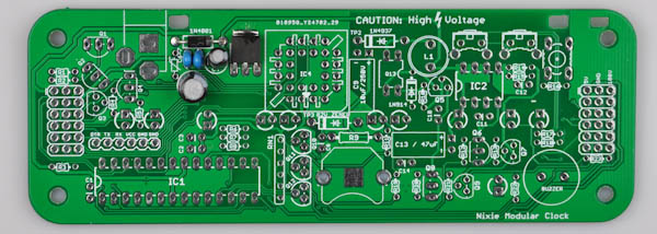
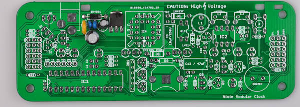
First, take some time to familiarize yourself with the Nixie Modular Clock Base Board:
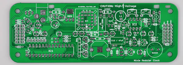

We will assemble the Board in a way that makes it easy to test that everything is working correctly along the way.
PART 1 - 5V Power Supply
We will assemble the components required for the 5V power supply first. This is the part of the circuit that takes the 9V input voltage and produces a nice stable 5V voltage that the microcontroller and the other perhiperals run off.
Required Components
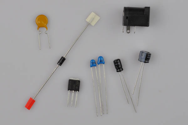
- 1x 2.1mm Power Jack
- 1x PTC fuse
- 1x 1N4001 diode
- 1x 47µF (small) (C4)
- 1x 100µF (medium) (C5)
- 2x 0.1µF Ceramic Capacitors (small blue) (C6, C7)
- 1x 7805 Voltage Regulator
NOTE: There are two 47µF capacitors included in the kit, use the smallest one here.
Step 1a
We'll start by inserting the 1N4001 diode in the footprint marked 1N4001 on the top left hand side of the PCB. There are several diodes, make sure you select the correct one.
It is black with a white stripe (there are two diodes like this). 1N4001 is written on the side.
Bend the legs of the diode 90 degrees to make it easy to insert. Take note of the white stripe on the diode: Orientation is important and it must be inserted so that the white stripe on the diode lines up with the white stripe on the PCB footprint.
After it is inserted properly (pull the legs with pinchers if you have trouble making the diode lie evenly against the PCB), bend the legs outward slightly.

Turn the board over and solder the two legs, then clip off the excess part of the legs with a flat wire clipper.

Most of the other two-legged parts, such as resistors, capacitors and other diodes are soldered using the same technique. Unless otherwise specified, use this assembly technique for the other two legged parts in the kit.
Step 1b
Next, place two of the blue 0.1µF ceramic capacitors into C6 and C7. Bend the legs to keep it in place, just like the diode.
Ceramic Capacitors are not polarized and can go in any way.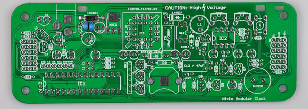
Step 1c
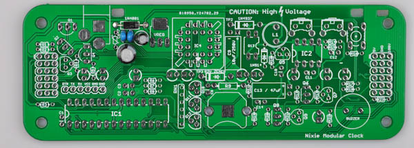
Next, the small 47µF electrolytic capacitor (C4) and medium 100µF (C5). These are normally black, but may also be other colors. The values are written on the side.
Make sure that the polarity is correct: The long leg of each capacitor goes into the square hole.
Step 1d
Locate the small 5V regulator, it goes to the spot marked VREG. Bend the legs 90 degrees and insert it so that it lies flat against the board.
Solder all three legs, and then add some solder on the top tab to secure it to the PCB board.
Step 1e
Now it is time for the PTC fuse. It is a large yellow disc with two legs. The kit also includes a two smaller yellow ceramic capacitors, so make sure not to mix them up.
It goes to the left of C6/C7, orientation doesn't matter.
Step 1f
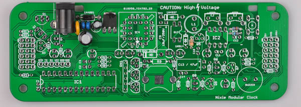
Time for the 2.1mm power jack connector. Insert it so that the hole points outward as in the picture. If it doesn't stay in place when you turn the board over, keep it in place with some masking tape.
Solder only one leg first, then check that the orientation of the component is correct. If not, re-apply heat and adjust as neccesary. Once you are happy with the orientation, solder the remaining legs.
Step 1g - Testing the 5V supply
Insert the power jack of the 9V power supply and then plug it in to the wall outlet. Locate your multimeter and set it to DC voltage metering.
On the right side of the board there are three holes marked 5V, GND, 180V.
Touch the black probe to the hole marked GND. Touch the red probe to the point marked 5V.
The multimeter should now read aproximately 5V. It will not be exact, but usually somewhere between 4.5V and 5.5V.
Remove the power jack from the device.
If the voltage was not correct, go back and double-check all component placement and solder points. Gently touch the yellow PTC fuse: If it is hot, it indicates that there is a short somewhere on the board.
DO NOT PROCEED TO PART 2 BEFORE YOU ARE ABLE TO VERIFY THAT THE 5V SUPPLY WORKS CORRECTLY.
PART 2 - 180V Power Supply
Now that we've verified that the 5V power supply works correctly, we'll continue on to the 180V power supply. The Nixie tubes need 180V to run, which is created by a DC/DC converter from the 9V input voltage.
IMPORTANT: Once this step is finished, whenever you apply power to the board it will generate 180V DC voltage. Be sure never to touch the board or work on it when power is applied. Always remove the power connector before doing anything else! After removing power, always wait at least 30 seconds before continuing work to allow the high voltage to dissapate.
Required Components
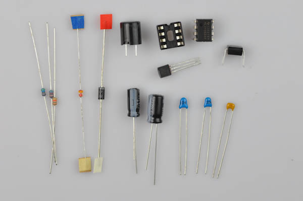
- 1x DIP-8 socket
- 1x MC34063 DC-DC converter (IC2)
- 2x 0.1µF Ceramic capacitors (small blue) (C10, C12)
- 1x 470pF Ceramic capacitor (small yellow) (C11)
- 1x IRFD110 MOSFET (Q13)
- 1x MPSA55 Transistor (number marked on transistor) (Q5)
- 1x 1N914 Diode (small red and yellow diode)
- 1x 1N4937 Diode(black, number marked on diode)
- 1x 2.2µF/250V Electrolytic Capacitor (C9)
- 1x 47µF Electrolytic Capacitor (C13)
- 1x 100uH Inductor (L1)
Resistors:
- 1x 1kΩ (Brown, Black, Red, Gold) 1/6W (R10)
- 1x 820kΩ (Gray, Red, Yellow, Gold) 1/4W blue (R14)
- 1x 5.6kΩ (Green, Blue, Red, Gold) 1/4W blue (R15)
Step 2a
Start by placing the resistors:
- 1x 1kΩ (Brown, Black, Red, Gold) 1/6W (R10)
- 1x 820kΩ (Gray, Red, Yellow, Gold) 1/4W blue (R14)
- 1x 5.6kΩ (Green, Blue, Red, Gold) 1/4W blue (R15)
If you are in doubt about the values, double-check with a multimeter. R14 and R15 set the output voltage of the DC/DC converter to produce 180V. Make sure not to mix them up, or the output voltage will be wrong!
Step 2b
Next, we will place the 1N4937 and 1N914 diodes:
- 1N4397 is black with a white stripe and has 1N4937 written on the side.
- 1N914 diode is smaller and is red with a yellow stripe.
Make sure the stripes line up with the stripes on the PCB. The footprints are in the upper right area of the PCB.

Step 2c
The next step is to place 3 more ceramic capacitors. This time there are two different kinds:
- 2x 0.1µF Ceramic capacitors (small blue) (C10, C12)
- 1x 470pF Ceramic capacitor (small yellow) (C11)
There are two yellow ceramic capacitors included: The 470pF is the smallest one. Again note that polarity does not matter for ceramic capacitors.
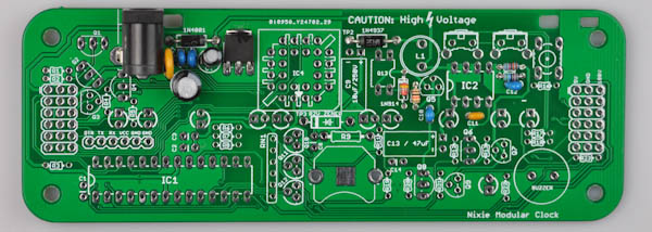
Step 2d
Find the 8-pin DIP socket, and insert it into IC2, so that the half-circle indentation matches the half-circle printed on the PCB footprint.
The component may fall out when you turn the board over to solder. You may use a small piece of masking tape or similar to hold it in place.Solder only one leg first, then check that the orientation of the component is correct. If not, re-apply heat and adjust as neccesary. Once you are happy with the orientation, solder the remaining legs.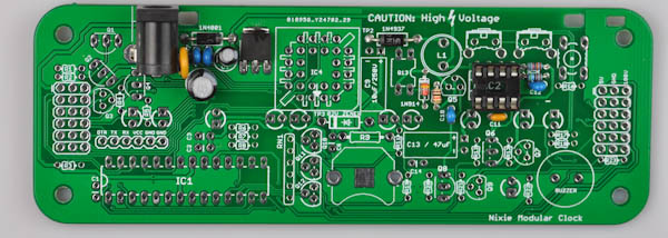
Step 2e
Next up is the MPSA55 transistor. There are many transistors included, so make sure to pick the correct one. It has MPSA55 written on it. It goes to Q5.
Transistors are polarized and must be inserted the correct way. The half-circle shape of the transistor should match up with the half-circle on the silk screen.Solder only one leg first, then check that the orientation of the component is correct. If not, re-apply heat and adjust as neccesary. Once you are happy with the orientation, solder the remaining legs.
Step 2f
Find the IRFD110 MOSFET. It is a square-shaped 4-pin DIP chip, that goes to Q13. The two legs on one side are connected together, make sure that the two connected legs are inserted into the two holes on the TOP side of the PCB footprint.

Step 2g
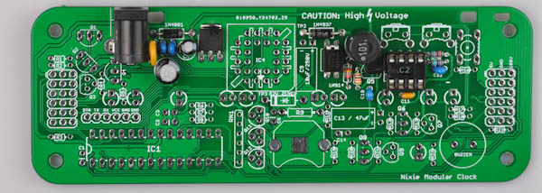
Next is the 100uH inductor, it is a small cylinder with two legs. The actual shape will vary: It will either be an enclosed plastic cylinder, or the coil will be visible. The footprint on the PCB is marked with L1.
This part is not polarized and can go in any way.
Step 2h
Next is the 2.2µF/250V electrolytic capacito, that goes to C9. Bend the legs 90 degrees before inserting.
Electrolytic Capacitors are polarized and must be inserted the correct way. The long leg goes in the square hole. The short leg goes in the round hole (marked with a minus sign)
Step 2i
Now find the long 47µF electrolytic capacitor, it goes to C13.
Electrolytic Capacitors are polarized and must be inserted the correct way. The long leg goes in the square hole. The short leg goes in the round hole (marked with a minus sign)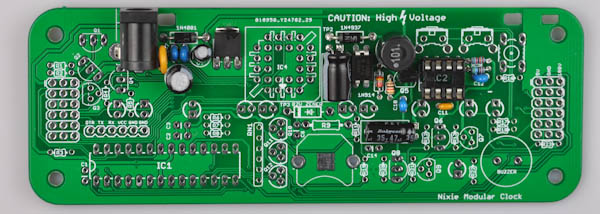
Step 2j
Find the MC34063 8-pin DIP chip. It is marked MC34063 or 063EC.
The IC chip must be fitted in the correct way. The half-circle (or dot) on top of the chip should match the half-circle marking on the silk screen / socket.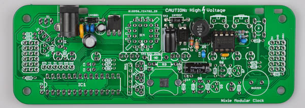
Step 2k
WARNING: From now on, whenever you apply power to the board, it will generate 180VDC. Never touch the board while it is powered up. If you touch an area with 180V it will be painful and potentially dangerous!
Now it is time to test the 180V power supply.
Insert the power jack of the 9V power supply and then plug it in to the wall outlet. Locate your multimeter and set it to DC voltage metering.
Locate the test point area on the top right of the board, the same one used earlier to test the 5V voltage.
First, touch the black probe to the hole marked GND and the red probe to the hole marked 5V. Verify that the voltage is still around 5V.
Next, move the red probe to the hole marked 180V, keep the black probe at GND. Be careful not to touch the probes together, as shorting the board at this point may damage components.
The voltage should read about 180V. (anything between 170V and 200V is ok)
DO NOT PROCEED TO PART 3 BEFORE YOU ARE ABLE TO VERIFY THAT THE 180V SUPPLY WORKS CORRECTLY.
PART 3 - 82V Power Supply
The next step is to add the parts required for the 82V power supply. This power supply is derived from the 180V power supply from the previous step. It is used for the HV5812 driver chip that is used to light up the Nixie tubes.
Required Components

- 1x 0.1µF Ceramic capacitors (small yellow) (C8)
- 1x 82V Zener Diode
- 1x 390kΩ (Orange, White, Yellow, Gold) Resistor (R9)
- 1x PLCC-28 socket (IC4)
Step 3a
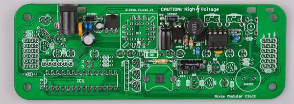
Solder the 390kΩ (Orange, White, Yellow, Gold) to R9.
Step 3b
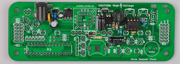
Next is the 82V Zener diode (the final remaining diode). Make sure the black stripe lines up with the white stripe on the PCB footprint.
Step 3c
Now it is time for the yello 0.1µF ceramic capacitors. It goes to C8.
Ceramic Capacitors are not polarized and can go in any way.
Step 3d
Find the PLCC-28 socket. Insert it so that the shape matches that of the PCB footprint.
The component may fall out when you turn the board over to solder. You may use a small piece of masking tape or similar to hold it in place.Solder only one leg first, then check that the orientation of the component is correct. If not, re-apply heat and adjust as neccesary. Once you are happy with the orientation, solder the remaining legs.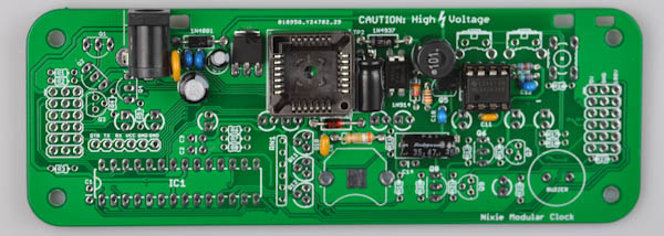
Step 3e
Now it is time to test the 82V power supply.
Insert the power jack of the 9V power supply and then plug it in to the wall outlet. Locate your multimeter and set it to DC voltage metering.
Touch the black probe to the GND pad as in the previous step. The left side of the Zener diode is marked TP3, touch the red probe here.
The voltage should read around 78-84V.
DO NOT PROCEED TO PART 4 BEFORE YOU ARE ABLE TO VERIFY THAT THE 82V SUPPLY WORKS CORRECTLY.
PART 4 - Misc Resistors
The Nixie Modular Clock requires a large amount of different resistors. In this step we'll place the remaining ones.
Be very careful to place all the resistors correctly according to value. Incorrect placement will lead to malfunction.
As before, the resistors can be identified by the color of the stripes, but when in doubt always double-check with a multimeter.
Required Components
- 3x 10Ω (Brown, Black, Black, Gold) (R16, R17, R18)
- 6x 300Ω (Orange, Black, Brown, Gold) (R6, R7, R8, R11, R19, R23)
- 1x 1.5kΩ (Brown, Green, Red, Gold) - (R22)
- 6x 10kΩ (Brown, Black, Orange, Gold) (R1, R2, R3, R5, R12, R20)
- 3x 470kΩ (Yellow, Violet, Yellow, Gold) (R4, R13, R21)
- 1x SIL6 resistor network 4.7k (RN1)
Step 4a - Resistors
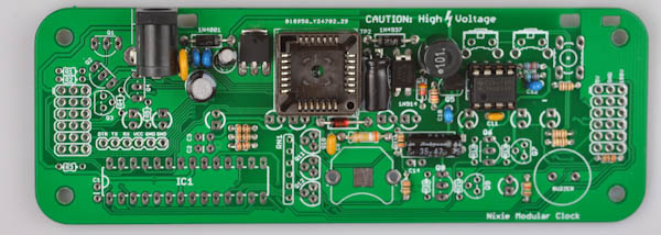
Sort all the remaining resistors and group the different values together:
- 3x 10Ω (Brown, Black, Black, Gold) (R16, R17, R18)
- 6x 300Ω (Orange, Black, Brown, Gold) (R6, R7, R8, R11, R19, R23)
- 1x 1.5kΩ (Brown, Green, Red, Gold) - (R22)
- 6x 10kΩ (Brown, Black, Orange, Gold) (R1, R2, R3, R5, R12, R20)
- 3x 470kΩ (Yellow, Violet, Yellow, Gold) (R4, R13, R21)
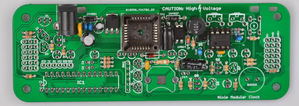
Carefully place each resistor to its correct place and solder. You may solder one at a time, or place several at once, and then turn the board over to solder.
Step 4b
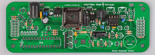
Next, find the 6-pin SIL 4700Ω resistor network, and place it in the footprint marked RN1.
Orientation does not matter.
PART 5 - Microcontroller and Misc
Next, we'll place the actual microcontroller and some supporting components
Required Components
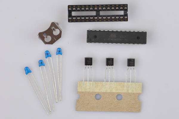
- 4x 0.1µF ceramic capacitors (C1, C2, C3, C14)
- 3x 2N7000 transistors (Q10, Q11, Q12)
- 1x 28-pin socket
- 1x Atmega328P microcontroller
- 1x Battery holder
Step 5a - Ceramic Capacitors
First up is to place remaining four blue 0.1µF ceramic capacitors. They go to C1, C2, C3 and C14, surrounding the IC1 footprint (C14 is next to the battery).

Step 5b
Now find the three 2N7000 transistors. They go in Q10, Q11 and Q12.
Be sure to orient them properly so that the half-circle shape matches that on the PCB footprint.

Step 5c
Next locate the footprint for the battery holder. It is in the lower right area. Melt a small amount of solder against the square pad in the middle: This will help get better contact with the real time clock backup battery.

Step 5d
Now place the battery holder, orient it so that it matches the drawing on the PCB footprint.
The component may fall out when you turn the board over to solder. You may use a small piece of masking tape or similar to hold it in place.This component will become very hot when soldering, so be careful when touching it.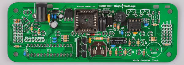
Step 5e
Next up is the 28-pin IC socket, to go into IC1.
Make sure to align it so that the half-circle mark on the socket lines up with the half-circle mark on the PCB (pointing left).
The component may fall out when you turn the board over to solder. You may use a small piece of masking tape or similar to hold it in place.Solder only one leg first, then check that the orientation of the component is correct. If not, re-apply heat and adjust as neccesary. Once you are happy with the orientation, solder the remaining legs.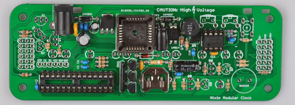
Step 5f
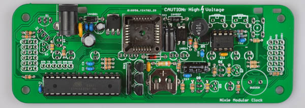
Now place the microcontroller in the 28-pin socket. Make sure the the half-circle indentation on the microcontroller lines up with the half- circle on the socket.
PART 6 - Nixie Anode Drivers
Next, let us place the high voltage transistors used to drive the Nixie Anodes.
Required Components
- 5x MPSA42 transistor (Q1, Q2, Q4, Q6, Q8)
- 3x MPSA92 transistor (Q3, Q7, Q9)
Step 6a
Start with the five MPSA42 transistors. The footprint of the MPSA42 transistors and the MPSA92 transistors are different to help differentiate where to place them. However, the actual transistors may be identical: Use the marking printed on them to tell them apart.
The MPSA42 transistors go to the footprints that have three holes in a row, and must be oriented so that the half-circle shape matches that on the PCB silkscreen.
Next are the three MPSA92 transistors, they have the number printed on them. They go in the Q3, Q7 and Q9 footprints, that have the holes spaced out like a triangle. Be sure that orientation is correct.

PART 7 - Buttons, Piezo and Other Components
Let us place the remaining components.
Required Components

- 6x 1x6 female header
- 2x Angled Buttons
- 1x Straight Button
- 1x HV5812 driver
- 1x CR1220 Battery
Step 7a
Place the 1x6 female headers in the left and right hand headers. These will be used to mount the display shield later on, so it important that they are aligned properly and 90 degrees to the board.

Step 7b
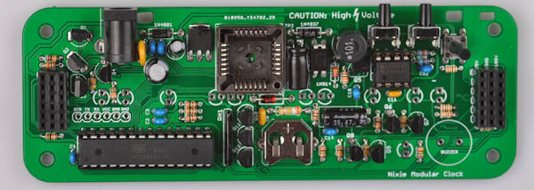
Place the buttons. They will click in place as you press them in.
Step 7c
Now insert the HV5812 chip in the socket. Look at the picture to match the orientation. Be careful not to insert it the wrong way as it is very difficult to remove from the socket once it has been placed.

Step 7d
Next, insert the battery, + pointing up.
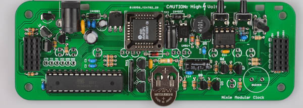
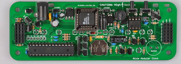
PART 8 - Remaining components
Required Components
- 1x 3mm round LED
- 1x Piezo Buzzer
Step 8a
Insert the Piezo Buzzer. The piezo is not polarized and can be inserted in any direction.
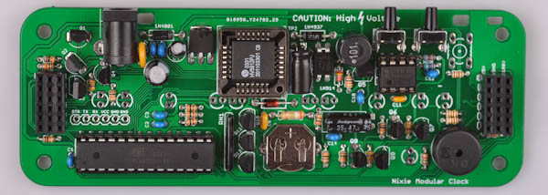
Step 8b
Find the single 3mm orange LED. It goes into the footprint in the lower right corner. Make sure that the long leg goes into the square hole on the PCB.

PART 9 - Final test
Apply power again: You should hear a sequence of beeps as the clock boots. Once you have confirmed that the clock boots properly, remove power.
NOTE: There are still open spaces on the base board for mounting LEDs. The amount of LEDs to mount and how to mount them depends on the display board, so we will assemble them together with the display board assembly.
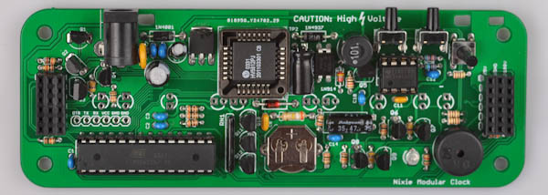
Continue with the display board assembly.