IV-22 Shield Parts List
- 1x IV-22 Shield PCB
- 6x IV-22 7-segment display tubes
- 2x 3.3V regulators
- 1x 2x9 pin male header
- 1x 2x10 pin male header
- 72x socket pins

IV-22 Shield Assembly
Step 1
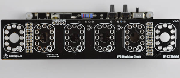
First take some time to familiarize yourself with the PCB. Each of the six IV-22 VFD tubes slide through the six mounting spaces on the PCB.
TOP VIEW:
BOTTOM VIEW:
Step 2: Headers
We'll start by soldering the headers that connect the display shield to the base board.
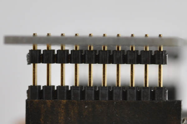
The long part of the legs go into the base board, insert them first, the 9-pin header goes on the left side, the 10-pin header on the right side.

Now place the display shield PCB on top, so that the short part of the legs go through the pin holes. Make sure the board is flat against the base board.

Solder all the pins.

Step 3: Regulators
Next, remove the display shield from the base board, and turn it over.

We will now insert the two 3.3V regulators from the bottom of the board. Make sure the regulators are inserted properly: The half-circle drawing on the board should match the half-circle shape of the regulator.

Turn the board over to solder, and then clip off the excess part of each leg.
PS: To the left of each of the two spaces for the voltage regulators, there are two headers that can house ceramic capacitors. These capacitors are optional, and are not included in the kit. They can optionally be populated with 0.1µF and 1µF ceramic capacitors.
Step 4: Pin sockets
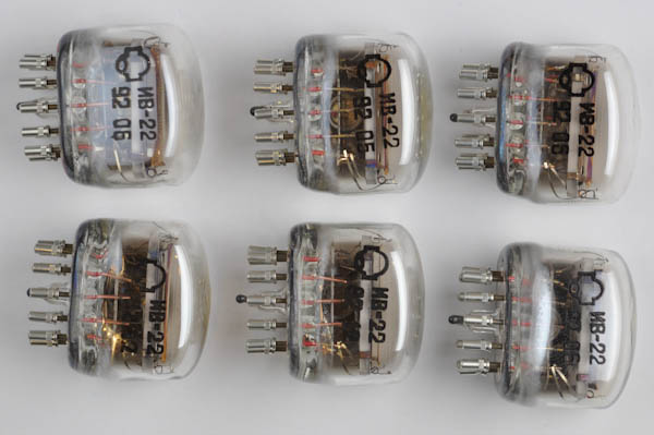
Now we will populate the legs of each IV-22 display tube with pin sockets. Make sure to press each socket as far in as it goes. You can use the blunt end of a screwdriver or similar for this.

PS: There may be 1-2 spare pin sockets left over.
Step 5: Placing the tubes
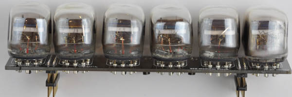
When all the pins sockets are properly inserted, it is time to insert the display tubes into the shield. The bottom right pin of each tube footprint of the board is marked with a white circle. Place each tube so that the decimal dot ends up here.
When inserting the tubes, press the sockets as far in as they go, and make sure each tube is evenly inserted before soldering. Carefully solder each of the 72 tube pins in place.


Congratulations! You have now completed the IV-22 display shield. When inserted into the clock it will be recognized as an IV-6 shield (since the IV-6 shield is also a 6-digit 7-segment shield)
Now Head over to theusage page for instructions on how to set the time.