VFD Modular Clock mk2 (version 2.0) - Repair Guide
We have discovered that some customers have issues with the clock running noticably slow (sometimes by as much as 15-20 minutes in one day).
The problem only applies to a small group of customers. If your clock is running normally, you do not need to perform any repairs.
The problem only applies to version 2 of the board, if you have the original version 1 board, this problem does not apply to you.
Description of the problem
The clock runs directly from a 5V USB plug. The 5V supply is used to power both the microcontroller and the on-board DS3231M real time clock (RTC). It is also used directly to generate the 40V high voltage used to drive the VFD tubes. This process generates extra noise on the 5V line, and depending on the power supply used, this noise coupled with the original noise from the power supply is enough to make the 5V power supply for the DS3231M chip so noisy that it runs incorrectly.
5V power adapters are more likely to give problems than when powering the clock directly from a computer or a USB hub.
Repair
To stabilize the power supply, we will add some extra capacitors and an EMI filter.
Step 1: Extra capacitors
First, remove the clock from the case if any, and remove the display shield.
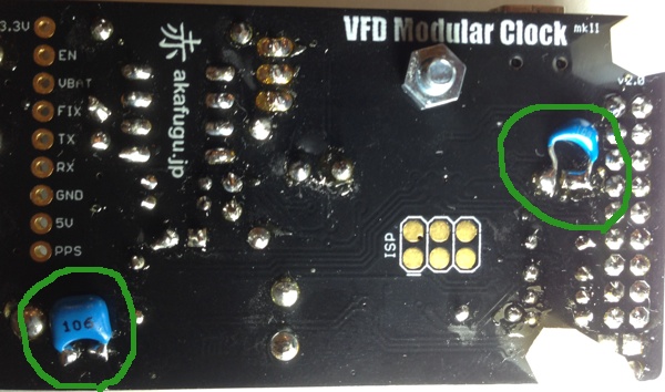
We will mount the extra capacitors on the bottom:
- 1µF - Marked 105 - Goes on the left
- 10µF - Marked 106 - Goes on the bottom right
First, cut the wires short. Use some masking tape to hold the the parts in place when soldering. Refer to the picture below for mounting:

Step 2: EMI filter (optional)
Normally, just adding the capacitors is enough to stabilize the RTC power supply, but the power supply can be further stabilized by adding an EMI filter on the USB input.
Before attempting this repair step, please take note of the following:
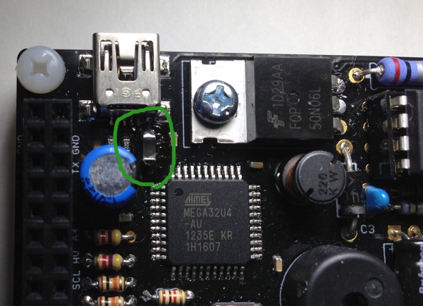
We will replace the onboard RTC fuse with an EMI filter. This means that the board is no longer protected from shorts. Under normal usage this is not a problem, but take care against shorting out anything.
The EMI chip is a small SMT part (1206 size). Removing the PTC fuse and replacing it is fairly difficult, so if you are not confident that you can perform this step, you may skip it.
First, we will remove the PTC chip: This can be done by adding some extra solder to each end. Alternate between heating up each and and use pinchers to slowly wiggle the chip upwards. Be careful against pulling too hard, as you may rip off the pad on the PCB. It is also possible to cut the chip in half with sharp wire cutters and then removing each end separatelty. If you use this method, you should still add extra solder to each pad first.

Next, use a solder sucker to remove the excess solder from the two pads.
Now, re-add some solder to the bottom pad, and pick up the EMI filter chip with pinchers. Keep the pad heated and push the filter chip down, making sure to align it properly. Now remove the soldering iron and keep the chip in place with the pinchers until it cools. Next add solder to the top pad.
How to get parts for repair
If your clock suffers from the issue descibed, please contact us by email with the following information:
- Your name and address
- Information about when you purchased the clock (order number if you ordered from our store, or name of shop otherwise)