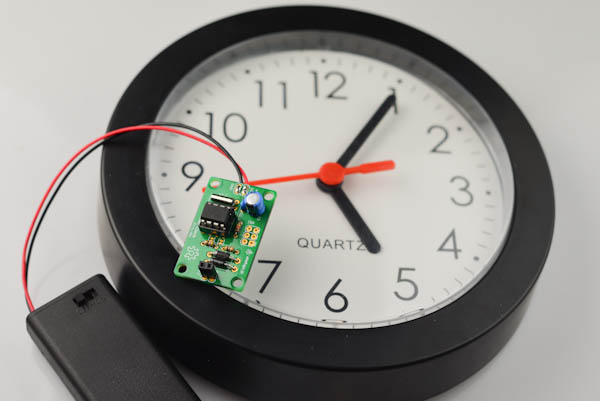
Once the clock is up and running, and you've reviewed the clock mechanism to make sure that it runs accurately (for instance by running it for a full day to see if it keeps good time), it will work pretty much as your unmodified clock.
If you're having any issues, check out the troubleshooting section below. We've also added a couple of firmware variants to play around with, see the variants section below for details.
BATTERY LIFE
The clock will run at least 3-4000 hours (125 to 166 days) on a set of alkaline AA batteries. In most cases it will run much longer.
When the battery voltage drops, the clock will start to move erratically, and eventually stop completely.
Be sure to limit the voltage to no higher than 3V to 3.3V. Higher voltage than this will cause damage to the clock mechanism, and it may fail after a few weeks.
To power from anything higher than 3.3V, please use a 3V or 3.3V regulator. The clock uses very little power, so a small 0.1A regulator with a simple 0.1uF ceramic cap and 10uF electrolytic cap is plenty.
To extend battery life, it is also possible to add an extra battery box of 2 AA batteries connected in parallel with the included battery box.
CURRENT CONSUMPTION
The firmware utilizes the idle sleep mode of the Attiny25 processor, so most of the time the processor spends in sleep mode, where it consumes about 75µA. It wakes up from sleep mode four times a second and then decides if it going to tick or not. If it ticks, it will draw around 0.4-0.6mA for a maximum of around 100ms.
For a worst case estimate, let us assume that the clock is consuming 0.5mA continously.
A normal cheap alkaline AA battery will have a capacity of around 1500mAh, we are using two cells, but in series to give a higher voltage, so the capacity at 3V is also around 1500mAh.
0.5mA continuous drain gives us 2100 hours, or 87 days.
This is a very conservative estimate, since for more than 75 % of the time, the current consumption will only be 75µA, so even doubling the resulting number to 175 days still gives us a fairly conservative estimate.
ACCURACY
The accuracy depends on the 32kHz crystal, which will change depending on ambient temperature. If even higher efficiency is desired it is possible to replace the crystal by a dedicated temperature compensated crystal, such as the DS32KHZ.
TROUBLESHOOTING
Most issues can be traced to the clock mechanism and the modification.
- (on most clock mechanisms) The minute hand will move slightly each time the second hand moves if it seems stuck, or gets stuck at some point during its rotation, this probably means that the hands are not properly attached.
Gently remove the hands and try to re-attach.
- If the clock doesn't tick at all this can mean either that your batteries are dead or too weak (check with a voltage meter! Less than 2V means that the clock will be unreliable, but it may vary depending on the type of clock mechanism you are using). If the batteries are not dead, it may indicate an issue with the clock mechanism modification: Try to re-open it and double check that all cogs are in their correct position and that nothing is broken or missing.
VARIANTS
There are some variants of the default firmware available on github.
Each variant is in a separate branch: to check out the particular branch, either select it on github and click the download zip link or do "git checkout
master - The default firmware. "Random" movement over 32-second intervals
normal_1pps - Test firmware that pulses once a second. Useful for testing if the clock mechanism is working properly
almost_normal - Pulses once a second most of the time, but will skip a second and then tick twice in a second once in a while (on average once a minute).
REPROGRAMMING
To reprogram the clock, an ISP programmer is required.
Note that the two microcontroller pins connected to X1 and X2 will interfere with the programming procedure when they are connected to the clock mechanism.
To allow reprogramming, follow ONE of the steps below
Alternative 1:
Remove the Attiny25 chip from the socket and connect it to a breadboard. Use jumper wires to connect the ISP header. For this to work, you will need an additional 32kHz oscillator connected to pins 2 and 3 for this to work.
Alternative 2:
Temporarily desolder the two wires connected to X1 and X2.
Alternative 3:
Using an exacto knife, carefully cut the two marked traces on the PCB:

This will cut the connection to X1 and X2, so the board can now be reprogrammed.
Once the reprogramming is done, bridge the connectors by melding a solder blob on each of the pads.

USAGE WITH OTHER CLOCK MECHANISMS
The firmware as supplied is usable with most clock mechanisms.
The clock mechanism is moved by sending pulses of alternating polarity on the two wires that are soldered on to the mechanism. The required pulse length will vary between different clock mechanisms, so if you want to use your Vetinari Clock PCB with another clock mechanism, it may be neccesary to reprogram the clock (see the above section).
In the firmware, file main.c, look for:
#define ENERGISE_TIME 35
(the original black clock mechanism shipped until the end of 2013 has ENERGISE_TIME set to 30).
- If the second hand seems to be stuck, try to increase the value.
- If the second hand moves very erratically, try to decrease the value.