IV-18 Acrylic Case Assembly
Here are the included case components. The acrylic plates have a protective seal on them that must be pealed off before assembly. The protective seal may be transparent on some pieces.
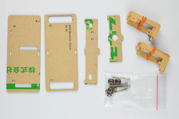
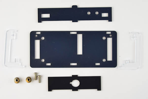
NOTE: This enclosure is only compatible with version 2 of the VFD Modular Clock base board.
Parts
2mm smoke gray acrylic plates:
- 1x bottom panel
- 1x top panel
- 1x front panel
- 1x back panel
3mm transparent acrylic plates:
- 4x left side panel
- 1x top left side panel
- 4x right side panel
- 1x top right side panel
The 3mm pieces look very similar, but there are subtle differences and they will not fit if they are mixed up.
There are two revisions available of the case.
Rev B. has a dot in the upper right corner of the right pieces to make them easier to tell apart. Refer to the following picture:
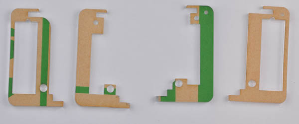
Older versions have R and L written on the pieces.
Screws:
- 2x M3-8 metal screws
- 2x M2 nuts
- 2x M3-25 metal screws
- 2x M2-25 metal screws
- 4x metal feet
You will need a screwdriver and the following bits to assemble the case:
- star bit
- allan 1.5 or torx 6 bit
Step 1
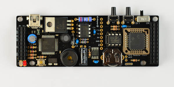
First, unplug the display shield and remove the plastic screws and spacers from your base board if present.
Step 2
Get the two M3 screws and two of the metal feet and fasten to the bottom board. Make sure the orientation matches the picture.
To keep the board level while working with it, get one more metal foot and slide it in underneath the bottom plate.
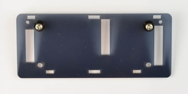
Step 3
Now insert the back panel so that the slots match the holes in the bottom board. It will fit comfortably only one way. Do not force it.

Step 4
Now get one left and right panel (there are four of each in total), and insert them.
They will stay attached to the back plate by pressure. Be careful not to press to hard or apply pressure at an angle as these parts are quite fragile.
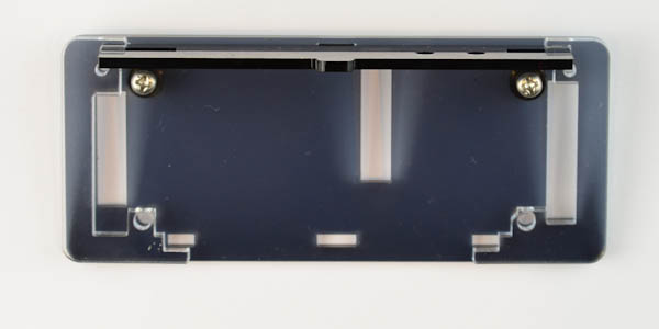
Step 5
Now insert the base board, aligning it with the screw holes on the bottom board.
It will not sit firmly until screws are attached in the last step.
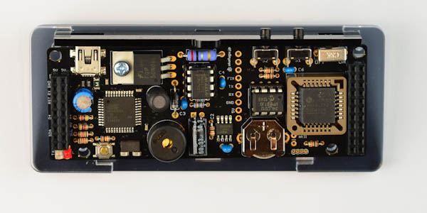
Step 6
Insert the front panel. Like the back panel, this panel looks symmetric, but it will only fit one way.
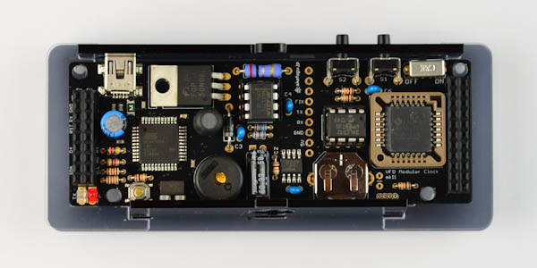
Step 7
Now, get the remaining four left and right side plates and slide them in (on top of the base board PCB).
Again, be careful, since the back tabs break off easily.
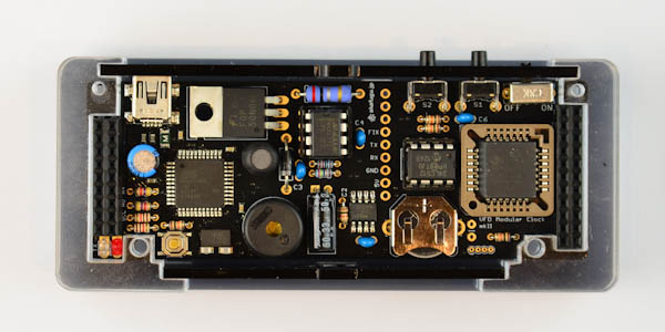
Step 8
Place the two larger left and right side plates on top. The stacked height should now be equal to the height of the front and back panels.
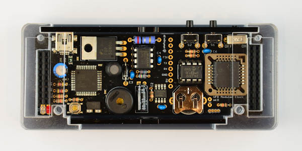
Step 9
Insert the top panel, orient it as shown in the picture. It will mate with tabs on the back and front plate.
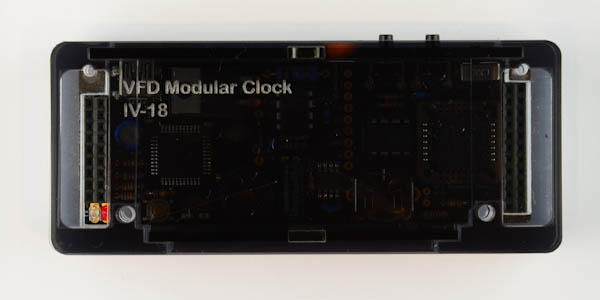
Step 10
Now it is time to insert the long M3 screws. Slide them in carefully correcting any misalignment of the side plates.
They are fastened underneath with the two remaining legs.

Step 11
The final step is to insert the two long M2 screws. The head of the screw should rest over the top plate.
Use the M2 nuts to tighten it underneath. (make sure not to tighten it too much)
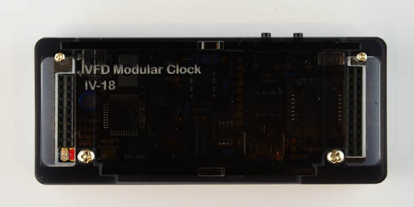
Finally, insert the left and right PCBs of the IV-18 display shield.