IV-18 Shield - Parts List
Included
- 1x IV-18 PCB
- 1x IV-18 support PCB
- 1x 2x9 pin angled male header
- 1x 2x11 pin angled male header
Not included
- 1x 1.6k resitor for the base board
- 2x Wire
IV-18 Shield Assembly (for VFD Modular Clock VERSION 1)
NOTE: The IV-18 shield was designed and released for version 2 (MK2) of the VFD Modular Clock base board.
If you have version 2 of the base board, go here:
These instructions are on how to adapt the board to work with version 1 of the base board.
Step 1
First take some time to familiarize yourself with the two PCBs.
--missing picture--
The PCB on the left goes into the left side of the base board. It works as a support for the long IV-18 tube, cradling i horizontally.
The PCB on the right is where the display tube is inserted. It goes to the right side of the base board.
Step 2
Locate the angled male headers.
- The 2x9 pin angled male header goes to the support board
- The 2x11 pin angled male header goes to the display board
First, clip off one row of pins from the 2x11 pin angled male header to make it into a 2x10 pin header.
Before soldering, look carefully at the picture below. The headers must be inserted exactly as shown:
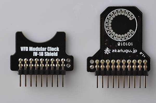
Insert the header, short legs go into the PCB, long legs are used for mounting on the base board. Make sure the alignment is as shown in the picture: Two pins should be left unconnected on both the boards.
Step 3
Do not solder any wires before step 5
Locate the display tube. There are three wires on the front that are not connected to anything inside the tube. These three wires must be cut off before mounting the tube on the PCB.
Take care to isolate the three correct wires, and double-check visually that they are not connected to anything inside the tube.
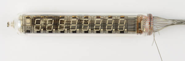
Here is the tube after cutting off the wires:
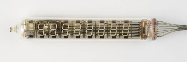

Insert the pin on top of the gap and below the gap into the display shield PCB:
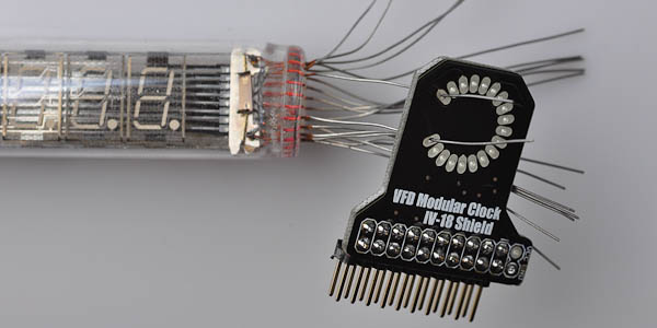
Make sure that the text that says "VFD Modular Clock IV-18 shield" goes on the back side.
Continue inserting wires one by one, making sure not to skip any wires.

Once all the wires are pulled through the correct holes, use pinchers to carefully pull the wires through the board, making sure to go gradually as you pull the wires. Be patient: By carefully pulling wires you can pull the display board up close to the back end of the board.
DO NOT SOLDER ANY WIRES YET.
Step 4
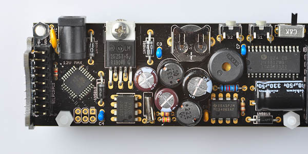
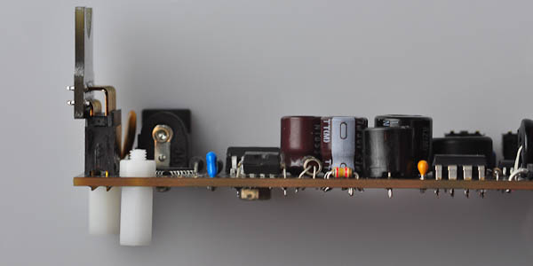
Insert the support shield on the left side of the base board as shown:
Step 5
Insert the display shield on the right side, and rest the IV-18 display tube on the support shield.

You can now start soldering wires. It is best to solder them with the display resting on the support board as this will ensure that the display is mounted horizontally. This is a bit tricky, since you will be soldering from an uncomfortable angle. The easiest is to start with the wire on top and bottom of where the 3-pin gap is. After soldering, clip off these two wires, then work your way around the board, clipping off excess wire as you go.
Step 6
On both boards, there are two unconnected pins left, marked VCC and GND respectively. Two wires must be pulled: one from VCC on the left to VCC on the right, and one from GND on the left to GND on the right.
It is best to cut the wire so that it is slightly longer than the span between the two PCB boards. That way the wires can be hidden from sight more easily.
Solder one side first, then pull the wire over to the other side and make adjustments to the length as neccesary.
Step 7
This step is optional.
PS: Versions of the base board that shipped since mid-2012 shipped with a 1.6kΩ resistor. Earlier versions of the board shipped with a 2.4kΩ resistor.
If your board already has the 1.6kΩ resistor, skip this step.
If your board has a 2.4kΩ resistor, the brightness of the IV-18 tube may be quite low. Changing it to a 1.6kΩ resistor will give higher brightness. We recommend first running the clock with the original resistor in place to see if you are happy with the brightness. (Remember to set brightness to 10 in the menu first)

Desoldering is a bit more tricky than soldering. You'll need the following tools:
- Pincher
- Wire clipper
- A solder sucker
There are many ways of desoldering. The following method works well for us:
Start by clipping off the existing resistor: Cut on each side of the mounting holes, close to the PCB. Take care not to damage the PCB silk screen.
Next, heat up one of the holes with your soldering iron, and gently pull out the remaining wire from the hole. It is easiest to do this from the back side.
The next step is to gently remove the remaining wire pieces from the holes. Heat up each hole and pull the wire out with your pinchers.
Finally, use the solder sucker to remove solder from the holes.
Now you can solder the replacement resistor.
Congratulations, you have assembled the IV-18 shield.
Now Head over to theusage page for instructions on how to set the time.