IV-18 Shield - Parts List
- 1x IV-18 PCB
- 1x IV-18 support PCB
- 1x 2x9 pin angled male header
- 1x 2x11 pin angled male header
IV-18 Shield Assembly (for VFD Modular Clock VERSION 2)
Assembly instructions for the IV-18 shield depend on which version of the base board and shield you have.
These instructions are for:
VFD Modular Clock base board mk2 (version 2) and IV-18 Shield v1.1
If you have any of the following combinations, follow the alternate instructions:
VFD Modular Clock base board mk2 (version 2) and IV-18 Shield v1.0
VFD Modular Clock base board original version and IV-18 Shield v1.0
Step 1
First, take some time to familiarize youself with the PCB:
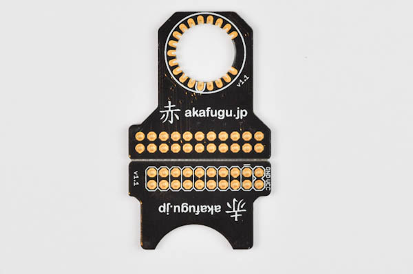
Break the PCB in two along the horizontal line. This can be done by hand by gently wiggling it back and forth.
We recommend using a piece of sandpaper to smooth out the edge of the two boards.

The small PCB on the left goes into the left side of the base board. It works as a support for the long IV-18 tube, cradling i horizontally.
The PCB on the right is where the display tube is inserted. It goes to the right side of the base board.
Step 2
Locate the angled male headers.
- The 2x9 pin angled male header goes to the support board
- The 2x11 pin angled male header goes to the display board
Before soldering, look carefully at the picture below. The headers must be inserted exactly as shown:
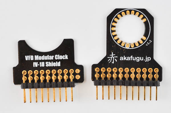
Insert the header, short legs go into the PCB, long legs are used for mounting on the base board. Make sure the alignment is as shown in the picture: Two pins should be left unconnected on both the boards.
Step 3
Do not solder any wires before step 5
Locate the display tube. There are three wires on the front that are not connected to anything inside the tube. These three wires must be cut off before mounting the tube on the PCB.
Take care to isolate the three correct wires, and double-check visually that they are not connected to anything inside the tube.
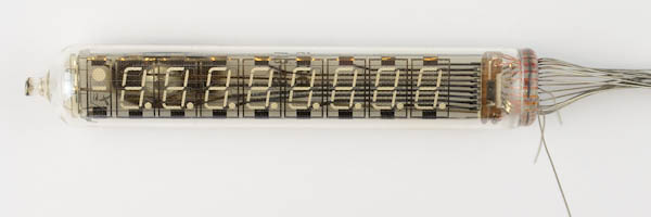
Here is the tube after cutting off the wires:
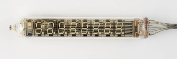

Now, press the remaining wires together, and push the entire bundle of wires through the hole in the middle of the display shield PCB. Align it so that the three wires you cut off line up correctly.
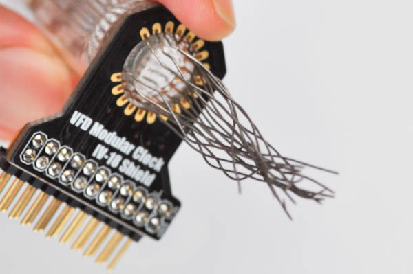
Make sure that the text that says "VFD Modular Clock IV-18 shield" goes on the back side.
Bend the wires out one by one, pulling gently so that each wire sits tight in the half-holes.
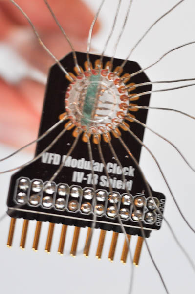
DO NOT SOLDER ANY WIRES YET.
Step 4
Insert the support shield on the left side of the base board as shown:
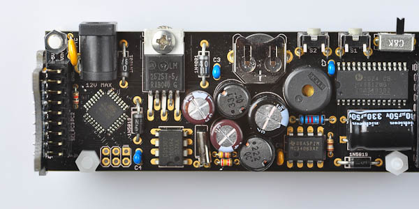
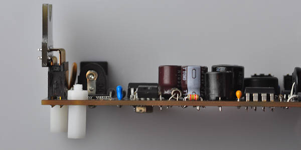
Step 5
Insert the display shield on the right side, and rest the IV-18 display tube on the support shield.

You can now start soldering wires. It is best to solder them with the display resting on the support board as this will ensure that the display is mounted horizontally. This is a bit tricky, since you will be soldering from an uncomfortable angle. The easiest is to start with the wire on top and bottom of where the 3-pin gap is. After soldering, clip off these two wires, then work your way around the board, clipping off excess wire as you go.
Congratulations, you have assembled the IV-18 shield.
Now Head over to theusage page for instructions on how to set the time.