Assembly Instructions
The LCD Candle comes as an easy to solder kit: It contains only a few parts and is suitable to beginners to soldering.
Requirements
To assemble this kit, you will need:
- A soldering iron
- Solder
- A wire cutter (a diagonal type that allows you to cut the wires as close to the soldering points as possible is best)
- Helping hands or clips to hold the PCB in place when soldering (a vise will also work)
- Pinchers
Optional:
- A multimeter
- Desoldering wick
- Solder sucker
- Protective glasses
See the equipment page for more details.
Preparations
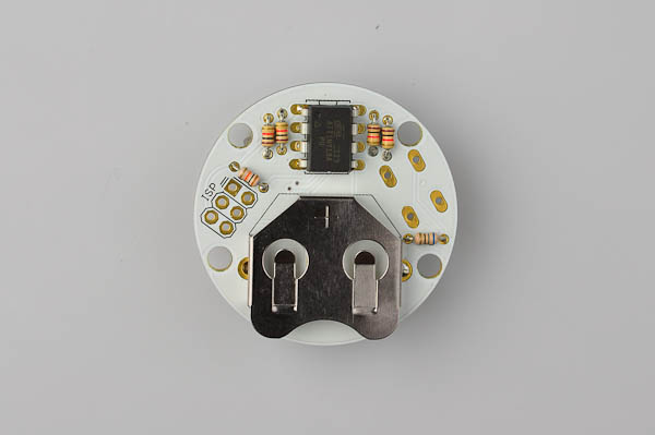
First, familiarize yourself with the PCB.
The top side comes with the LED attached:

All the components (except the button) are inserted in the back side of the PCB board (the side that does not come with any components attached).

Step 1
Let us start with the current-limiting resistors for the LED. There are four 1kΩ (Brown, Black, Red, Gold) resistors that go into the points marked R3 to R6. They have stripes that are brown, black, red, gold. If you are in doubt about the resistances, use a multimeter to measure (the 1kΩ and 10kΩ resistors look quite similar)
To insert each resistor, first bend its legs 90 degrees, then gently insert it into the two holes. Resistors are not polarized and can go in any way.

Pull the legs through and out on the other side, angle them so that the resistor does not fall out when you turn the board over. You can do one resistor at a time, or all four at once.
Turn the board over to solder the resistors in place.

Once the soldering is complete clip off the excess part of the legs with a wire clipper.

Step 2
Now let us place the two remaining resistors.
The 10kΩ (Brown, Black, Orange, Gold) resistor goes in R2. The 10Ω (Brown, Black, Black, Gold) (or 22Ω (Red, Red, Black, Gold)) goes in R1.
The resistors are soldered the same way as the resistors in step 1.

Step 3
Next place the processor, which is the black eight-legged chip. You will notice that it has a small dot on one side: The chip must be oriented so that the dot is in the adjacent to the half-circle printed on the PCB board.
Before inserting the chip, it may be neccesary to bend the legs slightly...

If the chip will not stay in place when you turn the board over, you can use a small piece of masking tape to keep it in place while soldering.

First solder one leg, then check orientation of the chip. If it does not lie properly against the PCB, re-apply heat and nudge it slightly until you are happy with the orientation. Now solder the remaining legs.
Step 4
The next step is to place the battery holder.
The central pad of the battery holder needs a bit of solder in order to make proper contact for the battery:
PS: Some boards are delivered with this blob of solder already in place. If yours already has solder, skip this part.

Place the battery holder. It should fit in to match the drawing on the PCB.
Step 5
All the components that go on the underside of the PCB are now placed. The next step is to turn the board over and place the tactile switch.
It is slightly rectangular, and fits according ot the drawing on the PCB. (if you mount it the wrong way, it will still work but will look a bit strange).

The button should stay in place when you turn the board over to solder.
Step 6
Find the four plastic legs and screws. Each leg goes in on the bottom and the screw goes in from the side with the LED on. Use a screwdriver, but be very careful not to pull to hard as the nylon screws and spacers are very easily damaged. Go slowly and make sure that that the screw and spacer are both straight.
Once the legs are in place, you'll need to place the battery. The + should point up:

Turn the board over: You should see the LED flickering.
Push the battery all the way in.

Turn the board over: You should see the LED flickering.
Congratulations: You have now assembled the Flickering LED Candle. Head on to the Usage Instructionsfor more information.
PS: It is easy to accidentally leave traces of solder flux on the PCB while soldering. These traces can sometimes be quite visible on light colored PCBs. It is possible to clean off the PCB with isopropyl alcohol (also known as rubbing alcohol).